PC Slower Than It Used to Be?
A free scan shows the junk files, broken settings and background clutter dragging Windows down - then fixes them in one click.Free scan · Windows 10 & 11Crashes, No Sound, or Screen Glitches?
Random freezes, missing sound and display glitches usually trace back to one bad driver. Find and replace yours safely.Free scan · under a minuteTo read an NES controller with an Arduino UNO, connect its power, ground, latch, clock, and data signals, then pulse latch and clock while reading eight active-low button bits. The sketch below reports A, B, Select, Start, Up, Down, Left, and Right in the Serial Monitor. This guide covers reading a controller with the UNO—not making the UNO impersonate a controller for an NES console.
What you need
- A classic 5 V Arduino UNO, such as the UNO Rev3. Its ATmega328P and digital I/O suit this simple interface; see the UNO Rev3 specifications.
- An original or NES-compatible controller. Compatible models may differ internally, so verify their connector signals rather than assuming the original wiring.
- An NES extension cable, mating breakout, or replacement controller cable, plus jumper wires. An extension cable or breakout lets you prototype without cutting a potentially valuable original controller cable.
- A USB cable to program the UNO. A multimeter is useful for checking cable continuity and power.
Do not connect an unidentified cable by wire color alone. Confirm the pinout before applying power; the controller plug and console-side socket can be viewed from opposite directions, making unlabeled pin diagrams easy to misread. NESdev documents the original port signals and notes that replacement wire colors are not universal: NES controller port pinout.
How the controller sends button states
Original-style NES controllers commonly use a 4021-family 8-bit parallel-in/serial-out shift register. The button contacts set its parallel inputs; the Arduino captures those states with a latch pulse, then clocks the register and reads one serial data bit at a time. The standard order is:
- A
- B
- Select
- Start
- Up
- Down
- Left
- Right
The first bit is available after latching; read it before the first clock edge. Each subsequent rising clock edge advances to the next button. See NESdev’s descriptions of the NES controller and controller reading sequence.
What’s actually slowing this PC down?
Pick the symptom - the matching free tool is one click away.
#1 Best Overall
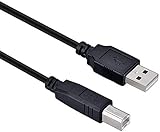
- High-quality shielded patch cable
- Arduino UNO USB Data Sync Cable for Arduino Mega 2560 Rev 3 R3 Microcontroller
- Cable lenght 3M
- What your Got is 1PCS with packaged cable
Button data is normally active-low: an unpressed button reads HIGH, while a pressed button reads LOW. The sketch inverts that signal by setting a bit when the data pin reads LOW. Thus a set bit in the returned byte means “pressed.”
Identify the five signals
| Signal | Other names | Purpose |
|---|---|---|
| +5 V | VCC, power | Powers the controller |
| GND | Ground, 0 V | Common electrical reference |
| Latch | OUT, strobe | Captures the current button states |
| Clock | CLK, pulse | Advances the shift register |
| Data | D0, serial out | Carries the button bits to the Arduino |
These names describe signals, not a universal cable color scheme. Verify each wire from the connector to the controller board or use a documented breakout. Do not use a diagram that shows numbered holes without specifying which side of the connector you are viewing.
Wire the controller to the UNO
With the UNO disconnected from USB while you wire, connect the verified signals as follows. The three digital pins are examples; other digital pins work if you also change the sketch constants.
Rank #2

- Original ATmega328P CH340 chip is used. Improved new version CH340G Replace FT232RL.
- LAFVIN Nano V3.0 card is 100% compatible with the Nano card, and fully compatible with Windows, Mac and Linux operating system.
- Works the same as original Nano, runs perfectly on programming software.
- Using Atmel Atmega328P-AU MCU, Support ISP download; Support USB download and Power.
- LAFVIN Nano CH340 controller is a compact board similar to the R3 board, smaller and breadboard-friendly than Diecimila.
| Controller signal | UNO connection | UNO pin mode |
|---|---|---|
| +5 V | 5V | Power |
| GND | GND | Ground |
| Latch | D2 | OUTPUT |
| Clock | D3 | OUTPUT |
| Data | D4 | INPUT |
Use the UNO’s 5V pin only with a controller whose voltage requirements you have verified. Avoid shorts between 5V and GND. For signal and port details, consult the NES port pinout and the UNO Rev3 documentation.
Do these 3 things before closing this tab:
1Repair Windows errors before they cause bigger problems2Fix the driver behind crashes, sound loss and screen glitches3Clear out junk files and repair common Windows errorsUpload a button-reading sketch
In the Arduino IDE, select the connected UNO board and port, then upload this sketch. It reads the first bit immediately after latching and before generating the next clock edge.
const byte LATCH_PIN = 2;
const byte CLOCK_PIN = 3;
const byte DATA_PIN  = 4;

enum Button {
  NES_A = 0,
  NES_B,
  NES_SELECT,
  NES_START,
  NES_UP,
  NES_DOWN,
  NES_LEFT,
  NES_RIGHT
};

byte readNESController() {
  byte buttons = 0;

  // Capture the current state of all eight buttons.
  digitalWrite(LATCH_PIN, HIGH);
  delayMicroseconds(12);
  digitalWrite(LATCH_PIN, LOW);

  // Read eight serial bits, A first.
  for (byte i = 0; i < 8; i++) {
    // Pressed buttons are normally active-low.
    if (digitalRead(DATA_PIN) == LOW) {
      buttons |= (1 << i);
    }

    // Rising clock edge advances to the next button.
    digitalWrite(CLOCK_PIN, HIGH);
    delayMicroseconds(6);
    digitalWrite(CLOCK_PIN, LOW);
    delayMicroseconds(6);
  }

  return buttons;
}

bool pressed(byte buttons, Button button) {
  return buttons & (1 << button);
}

void setup() {
  pinMode(LATCH_PIN, OUTPUT);
  pinMode(CLOCK_PIN, OUTPUT);
  pinMode(DATA_PIN, INPUT);

  digitalWrite(LATCH_PIN, LOW);
  digitalWrite(CLOCK_PIN, LOW);

  Serial.begin(115200);
}

void loop() {
  byte buttons = readNESController();

  Serial.print("A=");
  Serial.print(pressed(buttons, NES_A));
  Serial.print(" B=");
  Serial.print(pressed(buttons, NES_B));
  Serial.print(" Select=");
  Serial.print(pressed(buttons, NES_SELECT));
  Serial.print(" Start=");
  Serial.print(pressed(buttons, NES_START));
  Serial.print(" Up=");
  Serial.print(pressed(buttons, NES_UP));
  Serial.print(" Down=");
  Serial.print(pressed(buttons, NES_DOWN));
  Serial.print(" Left=");
  Serial.print(pressed(buttons, NES_LEFT));
  Serial.print(" Right=");
  Serial.println(pressed(buttons, NES_RIGHT));

  delay(20);
}
The 12-microsecond latch pulse and 6-microsecond clock phases are conservative example timings for this slow, human-operated input; they are not unique required values. A historical engineering lab reference gives microsecond-scale timing guidance, including a clock pulse of at least approximately 6 microseconds: NES controller lab reference.
Rank #3

- START CODING WITH A FLEXIBLE UNO R3 BOARD: Connect the included USB cable, upload sketches with Arduino IDE and build sensor, motor, display and automation projects for maker desks, classrooms, coding labs and electronics prototyping
- ATMEGA328P CORE FOR EVERYDAY PROJECTS: A 16 MHz clock, 32 KB flash, 2 KB SRAM, 1 KB EEPROM, 14 digital I/O pins with 6 PWM outputs and 6 analog inputs support LEDs, buttons, relays, servos, displays and sensors
- CH340C USB-TO-SERIAL INTERFACE: The onboard CH340C handles USB communication for sketch uploads and serial monitoring, while clearly labeled digital, analog and power headers help simplify wiring to modules and shields
- USB OR EXTERNAL POWER: Run the board from the included USB cable or a recommended 7-12 V external DC supply, then expand with compatible shields and modules for robotics, data logging, automation and custom embedded projects
- BOARD AND USB CABLE INCLUDED: Comes with 1 ELEGOO UNO R3 controller board and 1 USB-A to USB-B data cable; breadboard, jumper wires, sensors, shields and power adapter are not included
Check the readings in Serial Monitor
- Reconnect the UNO and upload the sketch.
- Open the IDE’s Serial Monitor and set its baud rate to 115200.
- With no buttons pressed, expect all eight fields to show
0. - Hold one button at a time and confirm that only its matching field changes to
1. Then test combinations.
Some official-style controllers return HIGH after the eighth button bit, but third-party controllers may behave differently on extra reads. This sketch reads only the eight standard bits, so it does not rely on that behavior.
Use the button states in your project
The returned byte uses bit 0 for A, bit 1 for B, bit 2 for Select, bit 3 for Start, bit 4 for Up, bit 5 for Down, bit 6 for Left, and bit 7 for Right. The pressed(buttons, NES_A) helper makes that mapping readable in application code.
Recommended Free Tools
Trigger an action once per press
Polling a held button repeatedly can retrigger an action. Compare the current state with the previous poll to detect a newly pressed button:
Rank #4

- Three Connector Types In One Kit: Includes 40 male-to-male, 40 male-to-female and 40 female-to-female jumper wires for connecting breadboards, female sockets, male headers, sensors, displays and controller modules during temporary prototyping
- 20 cm Length With Separable Ribbons: Each 8 in lead reaches across breadboards and nearby modules without excessive slack; use the 40-wire ribbons as grouped buses or peel off smaller sections and individual wires to match your project layout
- Color-Code Circuits & Troubleshoot Faster: Multicolored insulation makes power, ground, clock, data and control paths easier to identify during LED projects, sensor tests, classroom labs and repeated electronics experiments
- 2.54 mm Connections For Common Headers: Male pins fit compatible 0.1 in female sockets and breadboards, while female ends fit compatible 0.1 in male headers; insert connectors straight and check continuity if a signal becomes intermittent
- Copper-Clad Aluminum With PVC Insulation: The leads are designed for temporary low-voltage signal prototyping rather than mains or high-current wiring; they are not pure-copper wire, automotive jumper cables or a crimp-connector kit
byte previousButtons = 0;

void loop() {
  byte currentButtons = readNESController();
  byte newlyPressed = currentButtons & ~previousButtons;

  if (newlyPressed & (1 << NES_START)) {
    Serial.println("Start was newly pressed");
  }

  previousButtons = currentButtons;
  delay(20);
}
For continuous movement, use the current state instead of edge detection. Polling every 10–20 ms is a practical starting point. The latch-and-clock exchange is separate from switch debouncing: if a project reacts to noisy presses, accept a changed state only after it remains stable for several consecutive polls.
Choose how to handle opposite directions
Do not assume that only one direction can be active. If Up and Down (or Left and Right) are both reported, let the application choose a policy. For example, this code ignores a vertical direction when its opposite is also pressed:
bool up = pressed(buttons, NES_UP);
bool down = pressed(buttons, NES_DOWN);

if (up && !down) {
  // Move up
} else if (down && !up) {
  // Move down
}Troubleshoot incorrect or missing input
| Symptom | Likely cause | What to check |
|---|---|---|
| No buttons appear to work | Missing power or ground, wrong pin assignment, swapped latch and clock, or broken cable | Measure approximately 5 V between controller +5 V and GND; confirm shared ground, sketch pin numbers, data input, and signal continuity. Check that the device is an NES controller, not an SNES controller with a different connector or pinout. |
| Every button appears pressed | Data shorted to ground, data/ground confusion, incorrect pin mode, unpowered or damaged controller, or missed active-low inversion | Verify the data wire and ground with a continuity check, confirm the controller is powered, and retain the LOW-means-pressed test in the sketch. |
| No buttons appear pressed, although power is present | Floating or misidentified data, absent latch pulse, no clock transitions, or third-party wiring variation | Verify the data signal end to end and check that latch and clock toggle on D2 and D3. Print the raw result with Serial.println(buttons, BIN); or inspect signals with a multimeter or logic analyzer. |
| Buttons appear shifted by one position | The code clocks before reading the first bit | Read data immediately after latching, then pulse clock to advance to the next button. |
| Directions behave unexpectedly | Opposite directions can be active together, the application assumes exclusivity, pinout is wrong, or contacts are worn | Print the raw byte, test each direction separately, and define how the application handles simultaneous directions. |
| UNO resets when Serial Monitor opens | The UNO may reset when its USB serial connection opens | Wait for the sketch to restart and resume readings before treating the reset as a controller fault. |
Some PAL-region NES systems and accessories have protection diodes that make pull-ups on latch and clock relevant in console-connected setups. That is generally not the issue when the controller is connected only to the Arduino as described here; see the compatibility notes in the port documentation and controller reference.
Best Value

- START CODING WITH THE ELEGOO UNO R3: Connect the included USB cable, upload your first sketch, and build sensor, motor, display, and automation projects, making it a practical controller for maker desks, classrooms, coding clubs, and robotics labs
- ATMEGA328P CORE FOR EVERYDAY PROJECTS: A 16 MHz clock, 32 KB flash, 14 digital I/O pins with 6 PWM outputs and 6 analog inputs provide a versatile foundation for LEDs, buttons, relays, servos, displays and sensors
- RELIABLE USB PROGRAMMING AND CLEAR WIRING: The ATmega16U2 USB interface supports sketch uploads and serial communication, while clearly labeled headers help simplify connections to jumper wires, shields and modules
- POWER AND EXPAND YOUR WAY: Run the board from USB or a recommended 7-12 V external supply, then add compatible shields and modules for data logging, automation, robotics, test fixtures and custom electronics projects
- BOARD AND USB CABLE INCLUDED: Comes with 1 ELEGOO UNO R3 development board and 1 USB-A to USB-B data cable; breadboard, sensors, shields and power adapter are not included, and younger learners should work with an experienced adult
Should you use a library?
For one controller and three signal pins, direct code is short and makes the protocol easy to understand. A library can help when you want a reusable API or broader controller support, but confirm that its examples compile for your exact board and controller.
- NESControllerInterface is listed as version 1.0.3, with a package date of December 28, 2024. That listing is not, by itself, evidence of official Arduino maintenance or compatibility with every UNO setup.
- NicoHood’s Nintendo library documents a broader Nintendo-controller project, with supported devices primarily focused on GameCube and Nintendo 64; do not assume it is a dedicated NES solution.
For ordinary button polling, UNO digital pins are sufficient; interrupts are not necessary. Polling is simpler for a human-speed controller and avoids added timing and shared-resource complexity.
When the goal is USB gaming or console emulation
Reading an NES controller with an UNO and presenting a USB gamepad are different jobs. The basic sketch sends button information over the UNO’s USB serial connection; a computer-side program must translate that serial data into keyboard or gamepad input. The UNO R3’s USB connection does not automatically make it a HID gamepad: the board uses an ATmega328P for the sketch and an ATmega16U2 for USB-to-serial communication, as described in the UNO documentation and its official product page.
Options include using a host-side serial translator, reflashing the ATmega16U2 (a more complex change with added risk), choosing a board with native USB HID support, or using a purpose-built NES-to-USB adapter. Check operating-system support and whether an adapter presents as a standard HID gamepad. If instead you want the Arduino to act as a controller for an NES console, that is a separate project: the Arduino must emulate the controller’s latch, clock, and data behavior rather than read it.
Quick Recap
Product prices and availability are accurate as of the date/time indicated and are subject to change. Any price and availability information displayed on Amazon at the time of purchase will apply.



