Do these 3 things before closing this tab:
1Fix the driver behind crashes, sound loss and screen glitches2Repair Windows errors before they cause bigger problems3Scan for outdated or missing drivers - takes under a minuteSome links on this page are affiliate links: if you buy through them we may earn a commission, at no extra cost to you.
This project is an NES emulator assembled on breadboards, not a chip-for-chip Nintendo Entertainment System. UF-Evan’s build uses an ESP32-S3 to run the custom DIJI-NES emulator, an ST7789 TFT for video, a MAX98357A I2S amplifier for sound, and an SD-card reader for software storage. The Hackster feature reports performance of up to about 50 frames per second, but that figure is a project report—not proof of original-console timing or compatibility with every NES game.
That distinction makes the project more useful, not less: it is a practical way to study the NES’s CPU, PPU, APU, input, storage, and display problems as an embedded-systems project.
What “breadboard NES” means here
The finished machine is best described as an ESP32-S3-based embedded NES emulator with breadboard peripherals. The ESP32 does not contain an original Ricoh NES processor or graphics chip. Instead, DIJI-NES implements the console’s major functions in software and sends the resulting video and audio to modern modules. The project identity, creator, component list, emulator name, and reported frame rate are documented by Hackster.
SD card / ROM storage
          │
          ▼
      ESP32-S3
   ┌──────┼──────┐
   │      │      │
  CPU    PPU    APU
   │      │      │
   │      ▼      ▼
   │   ST7789  MAX98357A ── speaker
   │
   └── controller input
The breadboards provide visible, reconfigurable wiring. They do not recreate the electrical behavior of an NES motherboard.
#1 Best Overall

- 🔥【Dual Mode & High Performance】 The ESP32-S3 development board features integrated dual-core xtensa 32-bit LX7 microprocessor, clock speed up to 240 MHz, with 16MB Flash and 8 MB PSRAM. Perfect for Arduino IoT projects requiring stable wireless communication with ultra-low power consumption.
- 🔧【Easy Programming & Debugging】 Equipped with dual USB Type-C ports, this ESP32-S3 board supports both USB and UART modes for effortless programming, firmware flashing, and debugging.
- 🌐【Versatile Wireless Connectivity】 Built-in Wi-Fi (2.4GHz) and Bluetooth 5.0 (LE) dual-mode ensure seamless connectivity with a wide range of smart devices, making it ideal for IoT, smart homes projects.
- 🚀【Flexible Download Options】 Supports dual download methods — USB direct download or USB-to-serial download — offering flexibility and convenience for different development needs.Ideal for beginners and developers working with ESP32-S3.
- 🔋【Advanced Power-Saving Modes】 Designed for energy-efficient applications, with 3.3V SPI voltage, the ESP32-S3 board supports multiple low-power modes, allowing you to extend battery life based on different usage scenarios.
Why an original NES is much harder than a 6502 on a breadboard
The original console centered on a Ricoh 2A03 CPU/APU and a Ricoh 2C02 PPU, alongside memory, controller logic, clocking, and a cartridge interface. Engineering references describe these as interacting subsystems rather than a generic CPU-and-screen combination (system overview; engineering detail).
- CPU/APU: The 2A03 is 6502-derived, but NES behavior includes platform-specific details such as disabled decimal mode, interrupts, memory-mapped I/O, stack operation, and DMA interactions.
- PPU: Background tiles, nametables, scrolling, palettes, sprites, priority, sprite-zero hits, VBlank status, and timing all matter. Drawing a final bitmap is not equivalent to reproducing PPU behavior.
- Cartridge and mapper: Program and graphics data come through cartridge hardware. Mappers can change address decoding, bank switching, and timing; an SD card is not automatically an original cartridge interface.
- Controllers: NES input uses a latch-and-strobe protocol, not simply one independent GPIO per button.
- Audio: The original pulse, triangle, noise, and DPCM-related functions have timing and mixing behavior that software must reproduce.
Reverse-engineering work such as the emu-russia NES references illustrates why a literal hardware recreation is a substantial digital-design project. A bare 6502 cannot substitute for the complete CPU, PPU, APU, bus, and cartridge system.
What each part does
| Part | Role | Build notes |
|---|---|---|
| ESP32-S3 development board | Runs DIJI-NES and coordinates peripherals | Pin labels, flash, PSRAM, and board revision vary; do not assume every ESP32-S3 board is drop-in compatible. |
| ST7789 TFT | Digital RGB video output | It is a modern SPI-style display, not native NES composite video. Size, resolution, orientation, and color order must match the firmware. |
| MAX98357A | I2S digital-audio amplifier | Drives a speaker from digital samples; it does not recreate the NES analog output stage. |
| SD-card reader and microSD card | Stores ROMs or project assets | SPI wiring, chip-select configuration, card formatting, and power quality affect initialization. |
| Breadboards, jumpers, USB supply | Physical interconnect and power | Useful for learning, but long or loose wires can cause faults that look like firmware bugs. |
| Controller or buttons | Player input | Use the project’s supported interface and verified wiring; do not invent GPIO assignments. |
A multimeter is essential for power and continuity checks. A logic analyzer is optional but valuable when diagnosing SPI, I2S, controller, or timing problems.
Rank #2

- ESP32-S3-DevKitC-1-N16R8 SPI voltage: 3.3v, ESP32-S3-DevKitC-1 is an entry-level development board equipped with Wi-Fi + Bluetooth module ESP32-S3
- Most of the I/O pins on the module are broken out to the pin headers on both sides of this board for easy interfacing. Developers can either connect peripherals with jumper wires or mount ESP32-S3-DevKitC on a breadboard.
- The ESP32-S3-DevKitC development board equipped with ESP32-S3-DevKitC-1-N16R8, a general-purpose Wi-Fi + Bluetooth LE MCU module that integrates complete Wi-Fi and Bluetooth LE functions.
- ESP32-S3-N16R8 cable can be used: USB Type A to Type-C cable or CC cable Note the distinction between the commonly used USB A port to Type-C cable that can only be charged, which cannot be used for communication between YD-ESP32-S3 and the host.
- USB-to-UART Port and ESP32-S3 USB Port (either one or both), default power supply (recommended)
Build it as a sequence of small tests
The Hackster feature identifies the major hardware but does not expose a complete, verified pin map or current setup procedure. Use the creator’s repository, schematic, README, and build notes as the authority for GPIO numbers, libraries, board settings, and commands. A sensible bring-up order is:
- Confirm the board: Identify the exact ESP32-S3 variant, flash/PSRAM configuration, voltage levels, and USB connection.
- Make power safe: Connect a common ground, verify 3.3-V logic requirements, and check that breadboard power rails are continuous. Never hot-plug modules into an energized, uncertain circuit.
- Test video alone: Flash a minimal display test, then verify orientation, color order, reset, backlight, and refresh behavior.
- Test storage alone: Read a known-good microSD card and print directory or file information over serial before involving the emulator.
- Test audio alone: Generate a tone through I2S, confirm speaker wiring, and check for noise, clipping, or amplifier heating.
- Test controls: Confirm every button, latch/strobe behavior, pull-up or pull-down requirement, and debouncing.
- Run the emulator without audio: Start with a known-compatible test ROM or legally obtained homebrew. Establish stable video and input before adding sound.
- Add audio and measure stability: Watch for buffer underruns, crackle, dropped frames, and resets when display transfer, SD access, and audio run together.
- Only then package it: Shorten wires, add strain relief, and consider a soldered prototype or PCB after firmware behavior is stable.
What the emulator has to reproduce
CPU emulation
DIJI-NES must model registers, flags, addressing modes, stack behavior, interrupts, memory accesses, and NES-specific 6502-derived behavior. Instruction tests can pass while games still fail if peripheral timing is wrong.
PPU emulation
Compatibility depends on more than producing a 256×240-style frame. The NES’s visible NTSC game area is commonly treated as 256×224 within that timing. Scrolling transitions, sprite evaluation, sprite-zero hits, VBlank status, palette behavior, and CPU-visible PPU registers can all affect gameplay. A display that looks correct in a static demo does not prove PPU accuracy.
Rank #3

- 【Low-power performance】: The AYWHP ESP32-S3 Core development board integrates a 2.4 GHz Wi-Fi and Bluetooth 5 (LE) dual-mode communication module, perfect for Arduino Internet of Things (IoT) projects.
- 【Simple programming and debugging】: The ESP32-S3 module makes it easy to program and burn in your ESP32-S3 board via dual USB Type-C ports, with a choice of USB or UART modes.
- 【Multiple Power Saving Modes】: The ESP S3 development board supports multiple low-power modes, which can be configured according to different application scenarios to provide longer battery life.
- 【Dual download modes】: The ESP S3-1 module supports both USB direct connection download and USB to serial port download, providing more flexibility and convenience.
- 【Diverse connectivity options】: The ESP32-S3-1 supports dual-mode Wi-Fi and Bluetooth 5.0 (LE) connectivity for a wide range of smart devices, making it ideal for Internet of Things (IoT) applications.
APU emulation
The audio path must schedule the NES pulse, triangle, noise, and DPCM-related behavior closely enough for the target software. The MAX98357A simply amplifies the ESP32’s I2S samples; it does not provide NES sound generation. The available project description confirms that DIJI-NES targets the APU, but it does not establish complete support for every channel, effect, or expansion-audio feature.
Does it play NES games?
It is intended to run NES software through emulation, and the reported approximately 50-FPS result suggests a functional demonstration. However, “runs NES games” does not mean “plays the entire NES library.” Real compatibility depends on:
- CPU instruction and interrupt accuracy;
- PPU register and scanline timing;
- controller polling;
- APU implementation and audio buffering;
- supported cartridge mappers;
- ROM format and available memory; and
- NTSC/PAL assumptions.
Simple NROM-style homebrew or test software may work while games using uncommon mappers, timing tricks, expansion audio, or unusual hardware do not. A 50-FPS maximum is a performance observation attributed to the Hackster report, not an independent benchmark or compatibility guarantee. Record each tested title, mapper, video result, audio result, input behavior, and glitches rather than publishing a blanket compatibility claim.
Rank #4
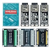
- 【ESP32-S3 PERFORMANCE】Dual-core 240MHz processor with 16MB Flash and 8MB PSRAM for IoT, AI, and machine learning projects.
- 【WIRELESS CONNECTIVITY】Onboard antenna for 2.4GHz WiFi and Bluetooth 5.0 LE — for smart home devices, no external antenna needed.
- 【LEAD-FREE GOLD EDITION DESIGN】Immersion gold (ENIG) plating for durability and conductivity. Lead-free, RoHS-compliant — for long-term prototyping.
- 【PRE-SOLDERED, PLUG-IN DESIGN】ESP32-S3 boards come with pre-soldered headers and plug directly into the included expansion and terminal boards — no soldering required.
- 【MULTI-PLATFORM COMPATIBILITY】Works with C++, MicroPython, ESP-IDF, Raspberry Pi, and STM32 — with online tutorials for quick start. Power via USB-C (5V) or VIN pin (5–12V); do not exceed 5V on the USB-C ports.
Breadboard failure modes
- Blank or corrupted display: Check ground, reset, backlight, voltage, SPI pins, orientation, and color-order settings. Different ST7789 boards can expose different connectors.
- SD initialization failure: Verify chip-select wiring, SPI mode, card formatting, shared-bus behavior, and supply stability. Keep SD wires short.
- Noisy or crackling audio: Check common ground, decoupling, speaker impedance, I2S pin configuration, and buffer scheduling. Digital amplifiers are sensitive to poor power layout.
- Controls do nothing: Verify the latch/strobe sequence, input pull resistors, connector orientation, and the exact GPIO mapping for your board.
- Random resets: Suspect weak USB cables, overloaded rails, shorts, brownouts, or amplifier current spikes before blaming emulation code.
- Game boots but breaks: Incomplete PPU timing, unsupported mapper behavior, sprite-zero handling, scrolling, or DMA emulation are likely suspects.
- Uneven frame rate: SD access, display transfers, audio generation, and emulation may contend for CPU time. Buffering and shorter wiring can help, but software scheduling remains central.
ESP32-S3 or FPGA?
The ESP32-S3 route suits readers who prefer C/C++ and iterative software work. It integrates storage, digital audio, and display control on an inexpensive development board, and breadboard wiring is approachable. Its weaknesses are shared CPU time, software-dependent timing, display-transfer overhead, and compatibility that rises or falls with emulator quality.
An FPGA can run CPU, PPU, memory, cartridge, controller, and video logic in parallel with deterministic timing. FPGA NES designs commonly divide the system along those boundaries, as shown in examples such as this architecture study and Dan Strother’s project. The trade-off is HDL knowledge, board-specific tools, and the need to implement display and audio interfaces yourself. An FPGA is an alternative learning path, not a drop-in replacement for this firmware project.
How to improve a working prototype
- Use a documented ESP32-S3 board and verified display breakout rather than an anonymous clone.
- Keep high-speed display and SD wiring short and route grounds deliberately.
- Add appropriate local decoupling and improve power distribution.
- Use buffering or double buffering where the software and memory budget permit.
- Move from solderless breadboard to a soldered prototype or custom PCB only after the emulator and pin map are stable.
- Use a logic analyzer when you need evidence about bus timing instead of guessing.
- Maintain a compatibility log rather than treating frame rate as a substitute for accuracy.
Legal and preservation considerations
Use self-authored homebrew, public-domain software, test ROMs, or game files you are legally entitled to use. An SD-card reader does not make commercial ROM downloading lawful. This is an independent hobby project, not Nintendo-approved or licensed hardware, and “NES clone” should describe the technical goal rather than imply endorsement.
Best Value

- 【GOLD EDITION — IMMERSION GOLD PCB】The Lonely Binary Gold Edition features a black PCB with lead-free immersion gold (ENIG) plating and clear silkscreen — the signature finish of the Lonely Binary Gold Edition line. RoHS-compliant.
- 【16MB FLASH + 8MB PSRAM】Large memory capacity for OTA updates, large programs, and AI/ML tasks — more headroom than 4MB boards for data-intensive IoT and automation projects.
- 【EXTERNAL IPEX ANTENNA】External IPEX antenna can be positioned for extended WiFi and Bluetooth signal coverage — for remote applications like weather stations, robots, or enclosed builds.
- 【DUAL USB TYPE-C PORTS】Separate power and data ports for macOS, Windows, and Linux. Power via USB-C (5V) or VIN pin (5–12V); do not exceed 5V on the USB-C ports.
- 【FLEXIBLE PROTOTYPING PINS】2x40-pin GPIO headers compatible with breadboards and sensors. Supports external ToF sensors via I2C for distance sensing.
Who should build it?
Build this project if you want to learn how an emulator maps CPU, graphics, audio, input, and storage onto a real microcontroller—and you are comfortable debugging both code and wiring. Choose an FPGA project if deterministic hardware timing is your priority. Choose a finished retro system if your priority is reliable play rather than understanding the implementation. For a durable device, prototype on breadboard first, then redesign the power, connectors, and enclosure around the tested firmware.
The Bottom Line
The breadboard NES is a compelling ESP32-S3 emulation project, not a literal reconstruction of Nintendo’s Ricoh chips or a guarantee of full-library compatibility. Its value is educational: it turns the NES’s CPU, PPU, APU, controller, storage, and video problems into a buildable embedded system. Reproduce it with verified project wiring and realistic compatibility expectations.
Quick Recap
Product prices and availability are accurate as of the date/time indicated and are subject to change. Any price and availability information displayed on Amazon at the time of purchase will apply.
What’s actually slowing this PC down?
Pick the symptom - the matching free tool is one click away.

