Verdict: The proposed Famicom RF-box replacement has a sensible overall layout, but it is a promising prototype—not a verified drop-in board. Before ordering a batch, resolve the conflicting 3.5-mm jack pinout, confirm compatibility with the exact console revision, and test the power rail, composite output, and audio mix under real loads.
What the replacement board must do
The Famicom’s rear power/RF assembly is more than an RF modulator. Depending on the console revision, a replacement may need to accept the external DC supply, route power through the console’s switch, provide regulated 5 V, connect through the existing ribbon cable, and add baseband composite video and mono audio. It also has to fit the shell and preserve the correct ground and signal paths.
The proposed design takes 9–10 V DC at a barrel input, uses a bridge rectifier and protection components ahead of an LM2596-5.0 buck regulator, filters an AV supply branch, buffers composite video with an NPN emitter follower, and passively combines internal and expansion audio for a 3.5-mm TRS output. Those blocks are plausible. Their actual performance depends on component selection, schematic details, PCB layout, the console revision, and measurements that are not established by the design discussion.
Check the Famicom revision before using a pinout
Do not treat “Famicom-compatible” as a universal fit claim. Existing replacement-board documentation distinguishes early five-pin and later seven-pin power/RF assemblies. It also notes different power-switch arrangements between board revisions and additional wiring for at least one HVC-CPU-GPM-02 installation. See the documented Famicom AV/power board configurations.
#1 Best Overall
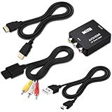
- 『Compatibility』This Nintendo 64/SNES/GameCube AV cable (6FT) delivers crystal-clear video(yellow) and stereo audio (red/white) through RCA connectors, exclusively compatible with Nintendo 64, Super Nintendo, GameCube and Super Famicom consoles - please verify your model before purchase.
- 『RCA to HDMI Converter』1080P Mini RCA to HDMI Converter Adapter Supporting PAL/NTSC for TV/PC/ PS3/ STB/Xbox VHS/VCR/Blue-Ray DVD Players.AV to HDMI converter no need any drivers, just plug to play.Please remember to hook up the USB power cable (included) to 5V power source to make it work.
- 『N64 AV Cable』The Video and Audio Cable are compatible with many TV games, suitable for Nintendo 64, GameCube, Super Nintendo SNES etc. (Support TV with RCA or HDMI Input.) Paired with the HDMI converter, it smoothly turns RCA output into HDMI input, perfect for connecting retro game consoles to modern displays.
- 『4K HDMI Cable 6 FT』The 4K HDMI cable supports ultra HD 4K@60Hz with 18Gbps bandwidth, backward compatible with HDMI 1.4/2.0 devices, perfect for modern gaming and home theater setups with plug-and-play simplicity.
- 『Simple 3-step Setup』Connect your console to the converter using the AV cable, link to your TV with the HDMI cable, power via USB, then switch to the correct HDMI input for instant HD retro gaming.
A pinout should name the exact board and show its numbering orientation. Identify, by continuity rather than assumption, ground, incoming or switched supply, regulated 5 V, composite, audio, and switch contacts. The switch may interrupt the raw input on one arrangement and a different rail on another. Ribbon orientation, length, mounting points, and connector height also matter. The available information does not establish a verified ribbon pinout for every Famicom motherboard revision, so do not copy a generic five- or seven-pin diagram onto an unidentified console.
- Record the motherboard marking and the original rear-board pin count before removal.
- Confirm whether the replacement routes the switch on the same rail as the original assembly.
- Check connector orientation and every signal path with a multimeter before applying power.
- State whether the board retains RF, disables it, needs jumper changes, requires extra wires, or needs case modification.
Regulator review: plausible topology, unverified implementation
The proposed power path is external 9–10 V DC, bridge rectifier, PTC fuse and clamp diode, LM2596 5-V buck regulator, bulk and bypass capacitors, then a ferrite bead feeding local AV decoupling. The designer lists an SS34 diode, inductor, and bulk capacitors in the switcher section, followed by 0.1-µF, 10-µF, and 47-µF capacitors on the AV side. These are proposed values, not evidence that the circuit is stable, quiet, or protected as assembled. The design discussion does not establish bench validation.
Before fabrication, check the exact LM2596 variant and its manufacturer-recommended inductor, catch diode, input/output capacitors, and capacitor ESR. Confirm that the chosen part is actually the fixed 5-V version if the design relies on a fixed output. Verify bridge orientation against the intended adapter polarity: a bridge can tolerate either DC polarity at its input, but its voltage drop consumes headroom and creates heat. Check the PTC hold/trip characteristics against normal console current and startup behavior, and verify the clamp diode’s polarity and rating. Do not call the protection effective unless its fault behavior is tested.
Rank #2
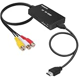
- RCA Female to HDMI Video Converters Adapter : The cable is used to convert analog composite input to HDMI 1080p output, displayed on a 1080p HD TV/TV/monitor.
- Input ports: 1xRCA Female (Yellow, White, Red), Output ports: 1xHDMI 1.3 1080p. NOT support 3D and 4K, NOT support HDMI Converts to AV
- AV to HDMI Converter: Plug and Play, Easy to Install and Operate, Powered by External USB Cable. Note: Please hook up the USB power cable (included) to 5V 1Apower source during use (not included power supply ).
- Support PAL, NTSC3.58, NTSC4.43, SECAM, PAL/M, PAL/N standard TV formats input. For PS2,PS3,Xbox,N64,STB, VHS, VCR, DVD Players and other devices with standard composite AV input.
- You Will Get : 1x RCA Female TO HDMI Converter, 1xHDMI cable, 1xUSB cable, 1xUser Manual. ONE YEAR WARRANTY - if you are not satisfied for any reason whatsoever, do not hesitate to contact us .
Layout is as important as the schematic. Keep the switcher’s input, diode, inductor, and output current loops compact. Do not route the video trace beside the inductor or switching node. Plan ground returns so the switching current does not flow through the video/audio reference path. Place local AV capacitors beside their loads. A ferrite bead is only useful if its impedance across the switching frequency and harmonics, current rating, and DC resistance suit the circuit; it cannot repair poor return-current routing.
Windows Errors? Fix Them Before They Spread
Repair common Windows errors and clear accumulated junk for a smoother, more stable PC - no reinstall needed.Free scan · no reinstallOutdated Drivers Are Slowing You Down
One free scan finds every outdated or missing driver and matches the right update for your exact hardware.Free scan · exact hardware matchA 7805 is simpler and can be an attractive repair when retaining the original board, but it dissipates the input/output voltage difference as heat. RetroRGB reported approximately 129 °F for an original regulator after 30 minutes and approximately 123 °F for a replacement board in one limited test setup; those figures depend on that supply and test arrangement, and are not general temperature guarantees. A buck converter can reduce regulator heat while adding ripple, EMI, layout sensitivity, and potential video or audio interference.
Power checks before connecting the console
- With the console disconnected, verify adapter polarity and measure its unloaded voltage. Confirm the bridge and protection-device orientation against the schematic.
- Power the board from a current-limited bench supply first. Check the 5-V rail at startup, idle, and under a representative console/game load; measure at the board output and at the console end of the ribbon.
- Measure ripple at both the regulator output and after the AV ferrite bead with suitable oscilloscope probing. A DC multimeter reading alone cannot establish a clean rail.
- Run the assembly for at least 30 minutes under gameplay load and monitor regulator, diode, and inductor temperatures. Repeat with the intended adapter; do not claim protection or thermal margin without the relevant fault/load tests.
Video buffer: verify bias and 75-ohm performance
The proposed video chain is a PPU composite source feeding a 2N3904-type NPN emitter follower, then a 220-µF coupling capacitor, a 75-Ω series resistor, and the composite output. A 1-kΩ collector resistor and 100-kΩ base-to-ground resistor are listed; an optional 220-pF shunt capacitor is also proposed. An emitter follower is a plausible buffer topology, but those values alone do not show that the transistor is biased correctly or that the output has the right amplitude and source impedance.
Rank #3
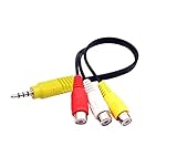
- RCA connectors provide composite video and stereo audio signal transmission.
- The av adapter work well connecting Game Consoles/ VHS/ VCD/ VCR/ DVD Player to TCL TV.
- TCL TV+AV adapter+male RCA cable, connect with other RCA device.
- The 3.5mm jack: Tip/ Ring/ Ring/ Sleeve iswired to Red /White /Ground /Yellow.
- Cable length: 6 inch.
Measure base, emitter, and collector DC voltages and estimate emitter current on the assembled board. Then examine the waveform at the emitter and at the output with a real 75-Ω load. Record composite amplitude, sync-tip and white-level amplitudes, black-level behavior, rise/fall time, ringing, overshoot, and noise. Test with both a television and a capture device; their inputs can reveal different weaknesses. A 75-Ω series resistor by itself does not prove that a terminated output will reach standard composite levels.
As a first-order estimate, 220 µF into 75 Ω gives a high-pass corner near 9.6 Hz: fc ≈ 1 / (2π × 75 Ω × 220 µF). Actual response also depends on source impedance, capacitor ESR, and the receiving input. The optional 220-pF capacitor has a nominal pole near 9.6 MHz with 75 Ω, but may soften transitions as well as reduce high-frequency ringing. Treat it as a value to evaluate on a scope, not as an automatic fit.
Quick wins for a faster PC:
Repair Windows errors before they cause bigger problemsFix Now →Fix the driver behind crashes, sound loss and screen glitchesFind Drivers →Clear out junk files and repair common Windows errorsFree Scan →Audio mixer: passive and intentionally unequal unless proven otherwise
The proposed mono mixer uses 47 kΩ from internal/APU audio and 100 kΩ from expansion audio, followed by a 1-µF coupling capacitor and an optional 100-Ω series resistor. This is a passive resistive mix, not an active summing amplifier. With equal source impedances and a high-impedance destination, the lower-value 47-kΩ branch contributes more strongly. Different source levels and impedances can change the result, so the values do not establish a balanced mix.
Rank #4

- Composite to HDMI Converter: Converts analog AV composite (Yellow, White, Red) input to HDMI 720P/1080P (60HZ) output, displayed on smart TV, Projector or HD Display, which bring back your old and cherish memories.
- Plug to Play: This HDMI Converter no extra drivers need, just plug and play,easy to use. Please hook up the USB Power Cable (included) to 5V power source during use. Note: The Video Converters only support converts AV to HDMI, can't converts HDMI to AV.
- Widely Used: This composite to hdmi adapter is widely applied to PS1, PS2, PS3, Xbox, N64, Wii, STB, VHS, VCR, DVD Players and other devices with standard composite AV input. Note: It can only be used when PS2 is set to RGB output.
- Wide Compatibility: This Video Audio Converter Adapter supports source formats of PAL, NTSC3.58, NTSC4.43, SECAM, PAL/M, PAL/N standard TV. Provide advanced signal processing with great precision, colors, resolutions, and details. Important Note: This converter can't improve video quality!
- Attention & Package: Please ensure to connect this av hdmi converter to power source to make it work. Package include: 1*AV to HDMI Adaptor, 1*USB Power Cable(adapter not included), 1*User Manual.
Measure internal and expansion audio separately, then together, at the intended output load. Check level, clipping, hum, crosstalk, and whether expansion audio remains audible across games with different channel strengths. The 1-µF capacitor’s low-frequency corner depends on the destination input impedance; a television, scaler, capture device, and adapter cannot be assumed to present the same load. If consistent relative levels are required, revise the resistor ratios from measurements or use an active mixer.
Resolve the TRS pinout before assembly
Do not order or connect a cable until the tip/ring assignment is fixed. The design descriptions conflict: one says tip is video and ring is audio; another reverses them, with sleeve as ground in both. This is a practical wiring hazard, not a cosmetic documentation issue. The same conflict is noted in the forum design thread.
- Select and document the exact TRS jack part number and its lug-to-contact mapping.
- Publish a labeled connector pinout and the matching TRS-to-RCA cable wiring. Do not rely on plug or RCA color conventions; one existing board report found video on the red RCA plug and mono audio on white.
- Before powering the console, use a continuity meter to trace tip, ring, and sleeve to the board’s video, audio, and ground nets.
- After power-up, confirm video and audio identities with a scope or known signal and a correctly wired breakout cable.
What the board can and cannot do about picture quality
Replacing the RF assembly can provide a convenient composite connection and remove the RF conversion path, but it does not automatically clean the motherboard’s video. Jailbars and other artifacts can originate in the console’s video generation and power/ground layout. The PCBWay project documentation warns that jailbars may become more pronounced after its composite upgrade. A board that outputs composite can therefore still show vertical bars, shimmer, or switching-related interference.
Free tools Windows power users keep installed
One-click scans. No signup required.
Best Value
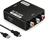
- Convert RCA to HDMI Instantly – BD&M RCA to HDMI Converter easily converts analog RCA/composite AV signals to HDMI output, allowing you to connect older devices to modern HDTVs, monitors, and projectors with clear video and audio quality.
- Wide Device Compatibility – Supports VHS players, VCRs, DVD players, camcorders, retro gaming consoles, and more including PS1, PS2, PS3, Xbox, N64, Wii, and older AV devices with standard RCA output.
- 1080P HDMI Output – Advanced signal processing delivers stable and sharp video output with support for 720P/1080P HDMI resolution, improving compatibility with modern TVs and displays.
- Plug & Play Setup – No drivers or software required. Simply connect the RCA cables, HDMI cable, and included USB power cable for quick and easy installation in minutes.
- Compact & Reliable Design – Lightweight mini converter design makes it perfect for home entertainment setups, retro gaming, travel, or converting old media collections while maintaining stable performance.
Separate the remedies: compare stock RF, a direct composite tap, the replacement board without motherboard changes, and a replacement plus a separately documented jailbar mitigation. Do not attribute a motherboard capacitor or PPU-video modification to the RF-box board, and treat PPU pin work as its own risk-bearing repair. RGB is a different goal: a NESRGB-class installation is more appropriate for readers seeking RGB output than a composite-only replacement.
Bench validation that supports a real compatibility claim
A responsible validation record should identify the board revision, console motherboard revision, adapter, load, measurement points, and instruments or termination used. Test more than one console revision before making a broad compatibility claim.
| Area | Test | Record or acceptance evidence |
|---|---|---|
| Power | Startup, idle, and gameplay load; measure at regulator and console rail. | 5-V readings, startup behavior, ripple before and after the AV bead, adapter used, and load condition. |
| Thermal | Run gameplay for at least 30 minutes in the intended enclosure. | Regulator, diode, and inductor temperatures plus ambient condition. |
| Video | Scope emitter and output into 75 Ω; test CRT, television, scaler, and capture input. | Amplitude, sync/white levels, black-level behavior, ringing, clipping, noise, and sync stability. |
| Audio | Test internal only, expansion only, and both together through a real cable and destination. | Relative levels, clipping, hum, crosstalk, and audible switching whine. |
| Compatibility | Install on identified five-pin and seven-pin variants and any specifically claimed motherboard revisions. | Pinout, switch behavior, jumpers/wires, fit, ribbon reach, and any case changes. |
| Mechanical | Fit the board in the closed shell with the cable and DC plug installed. | Thickness, mounting alignment, clearance, connector height, and absence of shell interference. |
For diagnostic isolation, power the AV section temporarily from a clean bench supply while keeping the switcher out of circuit. If interference disappears, investigate switcher layout, return paths, and filtering. If it remains, the source may be the console or buffer. Do not short outputs or defeat protection to force a test.
Alternatives for different repair goals
| Option | Best suited to | Trade-off |
|---|---|---|
| Repair the stock board and 7805 | Preserving original hardware and RF functionality. | Retains the RF limitation and linear-regulator heat; requires diagnosing the existing assembly. |
| Build this proposed PCB | Experimenters who want control over the circuit and can debug it. | Connector, load behavior, noise, and revision compatibility remain to be validated. |
| PCBWay shared AV/power board | Builders wanting an existing design with manufacturing files and assembly routes. | Its documentation still calls out revision-specific switch/jumper or wiring caveats and possible jailbars; it is not a universal novice drop-in. |
| BackOffice FC Power Amp / Famicom PSU-AV replacement | Readers seeking a ready-made composite/audio replacement with a no-cut objective for supported revisions. | Confirm exact console compatibility, connector wiring, current availability, and price with the vendor product page. RetroRGB’s review and limited thermal comparison also notes ribbon-cable desoldering can be difficult. |
| NESRGB-class installation | Readers whose actual target is RGB rather than composite. | More invasive and complex than replacing the rear power/RF board. |
The PCBWay project provides an open manufacturing route, but the documented revision caveats and jailbar warning remain relevant. The commercial BackOffice board may reduce circuit-debug work, but a no-cut objective is not proof that every Famicom revision fits. Current price and stock were not established here; check the vendor page before buying. Whatever route you choose, inspect the exact console and connector before desoldering the short ribbon cable.
Readiness verdict
The regulator, AV filtering, emitter follower, and passive audio mix form a credible architecture to review and prototype. The design is not yet demonstrated as stable, correctly leveled, quiet, safe under faults, or compatible across Famicom revisions. Resolve the jack wiring, publish revision-specific pinouts, confirm parts against the regulator datasheet, and collect loaded power/video/audio measurements before describing it as a finished replacement. Until then, the fairest label is electrically plausible and ready for another design-review cycle—not bench-validated or production-ready.
Quick Recap
Product prices and availability are accurate as of the date/time indicated and are subject to change. Any price and availability information displayed on Amazon at the time of purchase will apply.