What’s actually slowing this PC down?
Pick the symptom - the matching free tool is one click away.
The original Nintendo Switch Joy-Con is not simply a small Bluetooth gamepad. Each detachable controller is an asymmetric embedded computer combining buttons, calibrated analog input, a six-axis IMU, HD Rumble, battery management, firmware, and a wired rail interface. The right unit adds NFC and an infrared camera. Understanding it therefore requires both a hardware teardown and controlled analysis of its proprietary extensions to Bluetooth HID.
This guide covers the original HAC-015 left and HAC-016 right Joy-Con introduced in 2017. Nintendo says these controllers work wirelessly with Switch 2 but cannot attach directly to that console; Switch 2 Joy-Con 2 is a separate hardware family (Nintendo’s Joy-Con FAQ).
| # | Preview | Product | Price | |
|---|---|---|---|---|
| 1 |
|
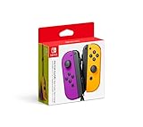
Nintendo Neon Purple/Neon Orange Joy-Con (L-R) - Switch | $87.95 | Buy on Amazon |
| 2 |

|
Nintendo Joy-Con (L/R) - Neon Red/Neon Blue (Renewed) | $63.84 | Buy on Amazon |
| 3 |

|
Nintendo Blue/Neon Yellow Joy-Con (L-R) - Switch | $93.70 | Buy on Amazon |
| 4 |

|
Nintendo Joy-Con (L)/(R) - Pastel Purple/Pastel Green | $87.00 | Buy on Amazon |
What “reverse engineering” a Joy-Con actually includes
A teardown answers where components are located, but not how the controller’s firmware and reports work. A complete investigation has several layers:
- Mechanical: opening the shell and documenting modules, screws, flex cables, antennas and rail contacts.
- Electrical: tracing power, charging, sensor, motor and wired-console connections.
- Firmware: examining the microcontroller, flash storage, calibration records and update behavior.
- Protocol: observing Bluetooth HID descriptors, input reports, subcommands, rumble and feature traffic.
- Application: converting raw reports into calibrated buttons, sticks, motion, haptics, NFC and IR data.
- Repair: diagnosing whether a fault is mechanical, electrical, software-related or specific to attached mode.
These are related but distinct goals. Decoding Bluetooth packets will not repair a worn potentiometer, and a successful teardown does not reveal Nintendo’s complete firmware or protocol specification.
Do these 3 things before closing this tab:
1Scan for outdated or missing drivers - takes under a minute2Clear out junk files and repair common Windows errors3Fix the driver behind crashes, sound loss and screen glitches#1 Best Overall
- Two Joy Con can be used independently in each hand, or together as 1 game controller when attached to the Joy Con grip
- They can also attach to the main console for use in handheld mode, or be shared with friends to enjoy two player action in supported games
- Each Joy Con has a full set of buttons and can act as a standalone controller, and each includes an accelerometer and gyro sensor, making independent left and right motion control possible
Scope: original Joy-Con versus Joy-Con 2
The subject here is the original detachable Joy-Con platform, including controllers used with the original Switch and Switch OLED. Nintendo’s current support information says original Joy-Con can pair wirelessly with Switch 2, but they cannot slide onto its console rails. Do not merge their report formats, rail hardware or menus with Joy-Con 2.
| Controller | Distinctive hardware | Primary input features |
|---|---|---|
| Left Joy-Con (HAC-015) | No NFC reader or IR camera | Directional buttons, minus, Capture, left stick, L/ZL, SL/SR, IMU and HD Rumble |
| Right Joy-Con (HAC-016) | NFC reader/controller and IR camera with illumination | ABXY, plus, Home, right stick, R/ZR, SL/SR, IMU and HD Rumble |
Inside the two asymmetric controllers
Both units contain a rechargeable lithium-ion cell, clickable analog stick, button membranes, Bluetooth radio, motion sensor, vibration actuator, charging circuitry and console-rail contacts. The right board has additional NFC and IR hardware, so a driver that assumes mirrored internals will need special cases.
In its examined hardware, iFixit identified these devices: a Broadcom BCM20734 Bluetooth 4.1/2.4 GHz transceiver, STMicroelectronics STM32P411 microcontroller, Macronix MX25U4033 4 Mb SPI flash, LSM6DS3H accelerometer/gyroscope, Texas Instruments BQ24072 charger/power-path IC, STMicroelectronics ST21NFCB NFC controller and a Rohm BD27400GUL component. These identifications describe the boards in that teardown, not a guaranteed bill of materials for every later revision or color (iFixit’s original Switch teardown; right Joy-Con teardown).
| Subsystem | What it contributes |
|---|---|
| Bluetooth transceiver | Wireless HID connection to a console or other host |
| Main MCU | Scans controls, manages peripherals, power states and protocol logic |
| SPI flash | Firmware and calibration records |
| LSM6DS3H-class IMU | Three-axis acceleration and three-axis angular velocity |
| Stick module | Two potentiometer axes plus a click switch |
| HD Rumble actuator | Independent left/right haptic output |
| Rail contacts | Power and console-side signaling when attached |
| NFC and IR assemblies | Right-controller-only accessory functions |
Tools and a safe teardown
Physical work commonly requires a tri-point Y00 driver, Phillips #00 or #000 driver, plastic opening picks, a spudger, tweezers, magnetic screw mat, isopropyl alcohol for suitable cleaning and soldering equipment for board repairs. iFixit’s Joy-Con index lists the relevant repair tools and parts (iFixit Joy-Con repair index).
Free tools Windows power users keep installed
One-click scans. No signup required.
- Photograph the exterior, labels, rail and screws; record left/right side, model marking, board revision and symptoms.
- Remove the four rear tri-point screws and separate the shell with a plastic pick. Do not yank the halves apart: battery wiring and ribbon cables remain connected.
- Disconnect the battery before manipulating the board or flex cables.
- Photograph cable routes, connector orientation, motor, antenna, stick, button membranes, rail and sensor boards.
- Record every chip marking and keep screws in their original positions; lengths and heads are not necessarily interchangeable.
- Inspect for torn flexes, pinched wires, damaged latches, crushed battery insulation and bent rail contacts.
- Before closing the shell, verify battery and cable seating, rail fit, stick movement, buttons, rumble and charging.
A lithium cell can be punctured, and the right controller’s extra assemblies make disassembly more involved. iFixit describes its teardown as disassembly rather than a complete repair recipe. If the unit still works and your goal is only protocol capture, begin non-invasively.
The Bluetooth HID layer
Joy-Con presents a Bluetooth HID interface, but its useful behavior extends far beyond a generic keyboard-style gamepad. Community documentation describes input reports, subcommand replies, calibration, battery and connection status, motion frames, rumble, NFC/IR payloads and firmware-update behavior. Nintendo has not published a complete public Joy-Con protocol specification.
| Report ID | Documented or observed role |
|---|---|
0x21 |
Input report used for subcommand replies |
0x23 |
NFC/IR MCU firmware-update-related report |
0x30 |
Standard full input mode with IMU data; notes describe normally pushed state at 60 Hz |
0x31 |
Standard input plus NFC/IR MCU data |
0x32, 0x33 |
Additional documented or partly understood input modes |
These labels and rates come from community reverse engineering, not Nintendo guarantees (Bluetooth HID notes). A report generally carries an identifier, timer, battery/connection information, button bitfields, both sticks, acknowledgment or subcommand data and, in relevant modes, multiple accelerometer and gyroscope frames. NFC and IR data use feature-specific payloads rather than ordinary button bytes.
Buttons and sticks
The button bytes are asymmetric: one primarily represents right-side controls, one is shared, and one primarily represents left-side controls. Face buttons, shoulders, SL/SR, Home, Capture, Plus, Minus, stick clicks and charging-grip status occupy documented bit positions. Decode and label those bits separately for left and right devices instead of assuming one universal map.
Stick values are raw readings, not ready-to-use axes. Calibration records in SPI flash define neutral offsets and usable ranges. A robust driver should retain raw values for diagnostics, then expose calibrated axes. The raw center need not be the numerical midpoint, and replacement modules can require recalibration.
Motion data
The six-axis IMU supplies three accelerometer and three gyroscope values, documented as signed 16-bit little-endian groups in several frames. Acceleration reflects movement and gravity; the gyroscope measures angular velocity. Orientation estimates require sensor fusion and accumulate error. Verify axis directions, signs, scale and timing experimentally for each implementation rather than assuming a universal physical-unit conversion.
HD Rumble
Rumble is a two-channel output problem, not an on/off switch. Commands encode frequency, amplitude and timing for left and right actuators. A driver should impose conservative limits and monitor battery voltage and reconnection behavior. A motor that spins proves only that some output path works; it does not validate the complete waveform encoding.
NFC and infrared
Only the right Joy-Con contains the NFC reader/controller and IR camera assembly. iFixit describes an IR camera with four IR LEDs. NFC and IR require different report handling and larger or feature-specific payloads, and neither is necessary for basic buttons, sticks or motion. Marketing descriptions of hand or object detection should not be treated as proof that every third-party host exposes the same capability.
Quick wins for a faster PC:
Repair Windows errors before they cause bigger problemsFix Now →Scan for outdated or missing drivers - takes under a minuteDriver Scan →Clear out junk files and repair common Windows errorsFree Scan →Rank #3
- Two Joy Con can be used independently in each hand, or together as 1 game controller when attached to the Joy Con grip
- They can also attach to the main console for use in handheld mode, or be shared with friends to enjoy 2 player action in supported games
- Each Joy Con has a full set of buttons and can act as a standalone controller, and each includes an accelerometer and gyro sensor, making independent left and right motion control possible
Wired rail communication
Attached to an original Switch or Switch OLED, a Joy-Con receives power and communicates through the side rail; detached, it uses Bluetooth. iFixit says interlocking contacts pass charging power and button information to the console motherboard. That does not establish a complete pinout or prove that application-layer traffic is identical to Bluetooth. Avoid publishing a rail schematic without measurements or an authoritative source.
Nintendo documents a real failure mode in which a controller works wirelessly but is not recognized while attached. Clean and inspect contacts, update console and controller software, detach and reattach, test another controller and, if possible, test the suspect unit on another compatible console before blaming the console rail (Nintendo attached-mode troubleshooting).
Independent reader supportYour contribution helps us test, update, and keep practical guides available for everyone.A reproducible reverse-engineering workflow
1. Establish the test subject
Log side, model number, firmware if available, hardware revision, shell variant and whether the fault concerns drift, pairing, battery, rail, buttons or motion. Never merge captures from unidentified revisions.
2. Record normal behavior first
- Pair with a supported Switch console.
- Test every button, both stick axes and stick clicks.
- Test motion, rumble, attachment, detachment and charging.
- On the right unit, test NFC and IR independently.
- Record battery behavior and any calibration screens.
Nintendo’s button test is at System Settings → Controllers and Sensors → Test Input Devices → Test Controller Buttons (official instructions).
3. Enumerate Bluetooth
On Linux or another low-level host, record the device name and address, HID service and descriptor, report sizes, input/output characteristics, pairing and automatic reconnection. Successful pairing does not imply that motion, rumble, NFC or IR is available.
4. Capture one known action at a time
Capture a button press and release, one stick axis, a stick click, rotation, shaking, rumble, a battery request, mode change and NFC activity. Timestamp and label every capture so timer increments, sensor frames and acknowledgments can be separated from background traffic.
Rank #4
- Expand your collection with these colorful pastel Joy-Con controllers.
5. Build a raw decoder before a polished driver
- Report ID and packet timer
- Battery and connection state
- Button bitfields
- Raw left and right stick values
- Accelerometer and gyroscope frames
- Rumble packets
- NFC/IR payloads
Apply calibration only after the raw layout is stable, then map values into a standard gamepad API.
6. Validate against console behavior
Check every button, neutral and full stick range, axis direction, Home/Capture handling, sleep reconnection, rumble stability, motion continuity and attached-mode differences.
The Tool Desk
Outbyte Driver Updater FREEScan for outdated or missing drivers - takes under a minuteDriver Scan →Outbyte PC Repair FREERepair Windows errors before they cause bigger problemsFix Now →7. Add features incrementally
Use this order: buttons, sticks, calibration, battery, motion, rumble, player LEDs, NFC, IR and finally firmware-related operations. The community notes describe OTA-related commands that can unlock erase/write behavior. Treat flash writes as potentially destructive; do not experiment on a valuable controller without a proven recovery plan.
Calibration, drift and diagnosis
Raw position, calibration and drift are different things. Raw position is the electrical reading. Calibration maps it to neutral and range. Drift is a persistent non-neutral value while the stick is released.
- Check whether the fault appears in Nintendo’s system input test or only in one game.
- Try software recalibration and observe whether neutral and range improve.
- Inspect for contamination or intermittent connectors without promising that cleaning will cure wear.
- If the released stick remains non-neutral, consider worn potentiometer tracks, springs, deformation or a failing flex.
- Choose a stick replacement, official service or replacement controller based on risk and value.
Calibration can correct an offset within the mechanical range; it cannot restore worn tracks, broken springs, damaged flex cables or a deformed module. A stick replacement is a repair operation, not a protocol solution. iFixit provides a left-stick procedure here: Left Joy-Con joystick replacement.
Common failure modes and research mistakes
- Mechanical: stripped tri-point screws, cracked tabs, torn flexes, pinched wires, damaged battery connectors, lost screws and broken latches.
- Electrical: charging failure, poor rail contact, antenna damage, disconnected motor, failed stick, corrosion or damaged NFC/IR subassembly.
- Protocol: pairing with incomplete reports, inverted motion axes, rumble-induced disconnects, changing report modes, firmware-dependent behavior and incorrect NFC/IR parsing.
- Methodological: unlabeled captures, treating timer bytes as timestamps, assuming report IDs are universal, confusing raw with calibrated data, copying packet tables without testing and writing flash before understanding recovery.
What remains undocumented
Public work does not establish a complete official protocol specification, full firmware architecture, every board-revision difference, a definitive rail pinout across revisions, all NFC and IR command semantics, universal sensor-unit conversions or guaranteed recovery from firmware-update commands. Community notes are valuable implementation evidence, but they should be tested against the exact controller and firmware being studied.
Repair, service or another controller?
| Situation | Practical choice |
|---|---|
| Working controller; protocol-only goal | Stay non-invasive and use Bluetooth/HID capture tools. |
| Single apparent drift fault | Test and recalibrate first; replace the stick only if physical wear is indicated. |
| Battery, rail or liquid damage | Consider official service before board-level repair. |
| Multiple faults or damaged board | A replacement or donor unit may cost less risk than repair. |
| NFC/IR investigation | Use a right Joy-Con; a left unit cannot substitute. |
| Firmware experimentation | Use a sacrificial controller and a documented recovery strategy. |
Nintendo’s U.S./Canada service page lists a one-year hardware/accessory warranty, requires proof of purchase for warranty service and excludes physical damage from standard warranty coverage; eligibility depends on region and current policy (Nintendo service information).
Quick Recap
Product prices and availability are accurate as of the date/time indicated and are subject to change. Any price and availability information displayed on Amazon at the time of purchase will apply.